Verilator Pt.1: Introduction

Verilator is a tool that compiles Verilog and SystemVerilog sources to highly optimized (and optionally multithreaded) cycle-accurate C++ or SystemC code. The converted modules can be instantiated and used in a C++ or a SystemC testbench, for verification and/or modelling purposes.
More information can be found at the official Verilator website and the official manual.
Why use Verilator? ⌗
Verilator is essentially a Verilog/SystemVerilog simulator. It’s commercial-grade, super fast, free and open source, but it is not a direct replacement for Modelsim, Questa Sim, Synopsys VCS, Vivado Xsim, and other event-based simulators. Verilator is a cycle-based simulator, which means it does not evaluate time within a single clock cycle, and does not simulate exact circuit timing. Instead, the circuit state is typically evaluated once per clock-cycle, so any intra-period glitches cannot be observed, and timed signal delays are not supported. This has both benefits and drawbacks when comparing Verilator to other simulators.
Speed ⌗
As Verilator is cycle-based, it cannot be used for timing simulation, back-annotated netlists, asynchronous (clockless)logic, or in general any signal changes that involve the concept of time - all outputs switch instantaneously whenever the circuit is evaluated.
However, because everything between clock edges is ignored, Verilator’s simulations run extremely fast and work great for simulating the functionality of synchronous digital logic circuits with one or multiple clocks, or for creating software models from your Verilog/SystemVerilog code for use in software development.
Code Quality ⌗
As verilator is cycle-based, it cannot fully support the IEEE Verilog and SystemVerilog standards. But don’t worry, synthesis tools are typically not fully compliant either.
Consequently, Verilator is very strict regarding the Verilog/SystemVerilog code you give it. Besides not supporting any time delays, it will also not accept most non-synthesizeable code*, so (typically) you cannot just take your SystemVerilog testbench and build it using Verilator without some significant modifications. You will get to know if Verilator doesn’t support your code quickly, as it will bombard you with heaps of warnings and error messages.
Because Verilator does not support unsynthesizeable code, there is the unexpected benefit of it being closer to the behavior of synthesis tools when compared to other simulators. It will force you to write better code for synthesis, potentially reducing the amount of problems you face later in the development process.
* with the exception of things like $display(), $finish(), $fatal(), some versions of $assert, and others.
Price ⌗
Verilator is open-source and free both as in free beer and free speech. To simulate a design using Verilator, a native binary executable is built from the verilated HDL code and the C++ testbench using GCC and Make. As the entire toolchain is free, there are no limitations on how many instances you can run or how many users can use it. Due to Verilator’s speed, simulations for even more complex designs complete quickly on older machines and laptops, thus you’re not required to purchase expensive computing hardware. Great for students!
Don’t let the price fool you, though. Verilator has a wide range of commercial users too:
 Fig. 1: Verilator users
Getting started ⌗
This guide is written for someone that primarily knows Verilog/Systemverilog and a bit of C/C++, but has never used Verilator.
I will assume you are using some form of Linux on your system, and have Verilator, GTKWave, Make, and GCC installed on said system.
You can get the finished sources for the example Verilator project used in this tutorial from Github and explore as you wish:
    git clone https://github.com/n-kremeris/verilator_basics
    git checkout verilator_pt1
Or, follow the guide below as we set up everything from scratch.
Our DUT ⌗
To check out how Verilator works, we need some kind of DUT (device under test). I wrote a basic ALU in SystemVerilog that we will verify in this multi-part tutorial series, the source of which is provided below:
/****** alu.sv ******/
typedef enum logic [1:0] {
     add     = 2'h1,
     sub     = 2'h2,
     nop     = 2'h0
} operation_t /*verilator public*/;

module alu #(
        parameter WIDTH = 6
) (
        input clk,
        input rst,

        input  operation_t  op_in,
        input  [WIDTH-1:0]  a_in,
        input  [WIDTH-1:0]  b_in,
        input               in_valid,

        output logic [WIDTH-1:0]  out,
        output logic              out_valid
);

        operation_t  op_in_r;
        logic  [WIDTH-1:0]  a_in_r;
        logic  [WIDTH-1:0]  b_in_r;
        logic               in_valid_r;
        logic  [WIDTH-1:0]  result;

        // Register all inputs
        always_ff @ (posedge clk, posedge rst) begin
                if (rst) begin
                        op_in_r     <= '0;
                        a_in_r      <= '0;
                        b_in_r      <= '0;
                        in_valid_r  <= '0;
                end else begin
                        op_in_r    <= op_in;
                        a_in_r     <= a_in;
                        b_in_r     <= b_in;
                        in_valid_r <= in_valid;
                end
        end

        // Compute the result
        always_comb begin
                result = '0;
                if (in_valid_r) begin
                        case (op_in_r)
                                add: result = a_in_r + b_in_r;
                                sub: result = a_in_r + (~b_in_r+1'b1);
                                default: result = '0;
                        endcase
                end
        end

        // Register outputs
        always_ff @ (posedge clk, posedge rst) begin
                if (rst) begin
                        out       <= '0;
                        out_valid <= '0;
                end else begin
                        out       <= result;
                        out_valid <= in_valid_r;
                end
        end

endmodule;
To follow this guide, create a new work directory, and save the ALU source as alu.sv.
As you can see, this ALU is very simple. It has two register stages, no stalling, and supports only two operations: addition and subtraction. Here is an example waveform of how we expect the ALU to behave:
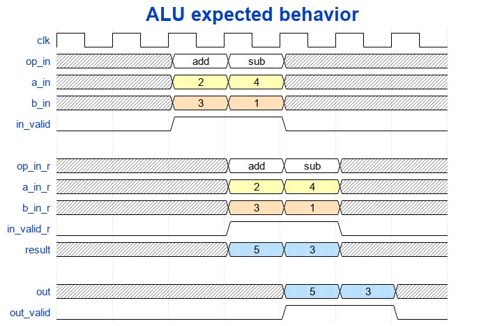 Fig. 2: Primitive ALU pipeline
From Figure 2, you can see that in the first stage, the input signals are registered, and in the second stage, the combinatorial result is registered into the outputs. With this in mind, lets now take a look at the steps needed to build a basic testbench.
SystemVerilog to C++ conversion ⌗
Verilation ⌗
As mentioned in the intro, Verilator requires a C++ testbench gets compiled into a native system binary. However, we cannot include our SystemVerilog ALU into a C++ testbench as-is: we first need to use Verilator to convert the SystemVerilog code into C++, or “Verilate” it, which in it’s most basic form is done as follows:
verilator --cc alu.sv
The --cc parameter here tells Verilator to convert to C++. Verilator also supports conversion to SystemC, which can be done by using --sc, but we will not be using this functionality for now.
Conversion results ⌗
Running the above command generates a new folder named obj_dir in our work directory. This is where all of our converted sources went:
$ ls -l obj_dir/
Valu___024unit.cpp  Valu___024unit__Slow.cpp  Valu.cpp  Valu.mk
Valu__Syms.cpp  Valu__ver.d Valu___024unit.h    Valu_classes.mk
Valu.h    Valu__Slow.cpp  Valu__Syms.h    Valu__verFiles.dat
The generated .mk files will be used with Make to build our simulation executable, while the .h and .cpp files contain our C++ headers and implementation sources, resulting from the SystemVerilog conversion. I suggest you to explore for a bit and see if you can figure out what is where.
The two files we’re most interested right now are Valu.h and Valu___024unit.h:
-
Valu.h- This is the primary design header which contains the converted “ALU” class definition - this is what we will “instantiate” in our C++ testbench as the DUT. -
Valu___024unit.h- This is an internal header for the “ALU” class, and it contains ouroperation_ttype definition.
Designing a basic Verilator testbench ⌗
Example C++ testbench ⌗
Now that we have our DUT converted to C++, we can start writing our testbench. Our testbench will be in a new file named tb_alu.cpp. Let’s start by exploring a minimal C++ testbench code example:
#include <stdlib.h>
#include <iostream>
#include <verilated.h>
#include <verilated_vcd_c.h>
#include "Valu.h"
#include "Valu___024unit.h"

#define MAX_SIM_TIME 20
vluint64_t sim_time = 0;

int main(int argc, char** argv, char** env) {
    Valu *dut = new Valu;

    Verilated::traceEverOn(true);
    VerilatedVcdC *m_trace = new VerilatedVcdC;
    dut->trace(m_trace, 5);
    m_trace->open("waveform.vcd");

    while (sim_time < MAX_SIM_TIME) {
        dut->clk ^= 1;
        dut->eval();
        m_trace->dump(sim_time);
        sim_time++;
    }

    m_trace->close();
    delete dut;
    exit(EXIT_SUCCESS);
}
The first few lines with the include statements are mostly self explanatory. We need to include <verilated.h> and <verilated_vcd_c.h> that come with the Verilator installation to access common Verilator routines and write waveforms to a VCD (value change dump) file.
As described previously, "Valu.h" contains the top class of our Verilated ALU module, and "Valu___024unit.h" contains a Verilated version of our typedef enumeration.
Next up, we’ve got the following two lines:
#define MAX_SIM_TIME 20
vluint64_t sim_time = 0;
We’ll use the sim_time variable to track when to finish the simulation. There are more ways to end a simulation, but for now, we’ll simply quit once we’ve simulated 20 clock edges.
Then we’ve got the following mess of a main function, which will look peculiar if you’ve not written a C++ testbench before:
int main(int argc, char** argv, char** env) {
    Valu *dut = new Valu;

    Verilated::traceEverOn(true);
    VerilatedVcdC *m_trace = new VerilatedVcdC;
    dut->trace(m_trace, 5);
    m_trace->open("waveform.vcd");

    /* <...> */

    m_trace->close();
    delete dut;
    exit(EXIT_SUCCESS);
}
The line Valu *dut = new Valu; instantiates our converted ALU module. In SystemVerilog, this would roughly equate to alu dut (.*);.
The next four lines set up the waveform dumping. Notably, we create an m_trace object and pass it on to our dut in the line dut->trace(m_trace, 5);. The parameter 5 simply limits the depth of the trace to 5 levels down the device under test.
Lastly, we’ve got the stuff that makes the simulation happen:
while (sim_time < MAX_SIM_TIME) {
    dut->clk ^= 1;
    dut->eval();
    m_trace->dump(sim_time);
    sim_time++;
}
During each iteration of the while loop, the line dut->clk ^= 1; inverts the ALU clock (This will create the rising/falling edges on the clock). This will be the one and only clock we’ll be using in our testbench.
The call dut->eval(); evaluates all the signals in our ALU module, and m_trace->dump(sim_time); writes all the traced signal values into our waveform dump file. As you can see, the model is currently only evaluated at the clock edges.
The simulation time is then incremented and the loop continues until it reaches MAX_SIM_TIME. Note that this is not actually a time value - the variable simply keeps track of how many times we’ve inverted the clock.
As you can see, this testbench doesn’t do much else besides clocking the design, but it’s a good starting point to build upon.
Building the simulation executable ⌗
Now that we have our testbench written, we need to build an executable to run the simulation.
Unlike some other simulators, for example Modelsim, in which you either open the sources in the graphical interface or pass them to the Modelsim executable, the Verilator application is not used to simulate the testbench.
Instead, the Verilator application is only used for converting Verilog to C++ and create build instructions for Make. The simulator in this case is the C++ testbench itself.
The testbench and the converted HDL sources are essentially a C++ application, which that gets built and run on your computer. Running the compiled executable is what simulates your design, and the GNU Compiler Collection (GCC) is the primary choice for building Verilator executables.
To build the simulation executable, we need to run Verilator again to regenerate the .mk files to include the C++ testbench - this is done using --exe tb_alu.cpp:
$ verilator -Wall --trace -cc alu.sv --exe tb_alu.cpp
Additionally, we’re now using the following extra parameters:
-Wall- turn on all C++ warnings. Not required, but useful when you’re just starting out--trace- enable waveform tracing
To build our executable we do the following:
$ make -C obj_dir -f Valu.mk Valu
-C obj_dir tells make to work in the obj_dir directory. We then pass the required makefile using -f Valu.mk. Lastly, we tell make to build the target Valu, which is the name of the compiled testbench executable.
If the testbench executable was built successfully, you will find a Valu binary in obj_dir.
Running the testbench ⌗
Once built, simply run the Valu binary to run the simulation:
$ ./obj_dir/Valu
$
At a glance, it doesn’t look like it did much. After all, we do not have any print statements in our testbench code, so it’s expected. However, running the simulation resulted in a waveform file named waveform.vcd being generated in our work directory.
Viewing Verilator waveforms ⌗
You can open the aforementioned Verilator waveform dump file using GTKwave:
gtkwave waveform.vcd
You will then be presented with a GTKWave window that looks like this:
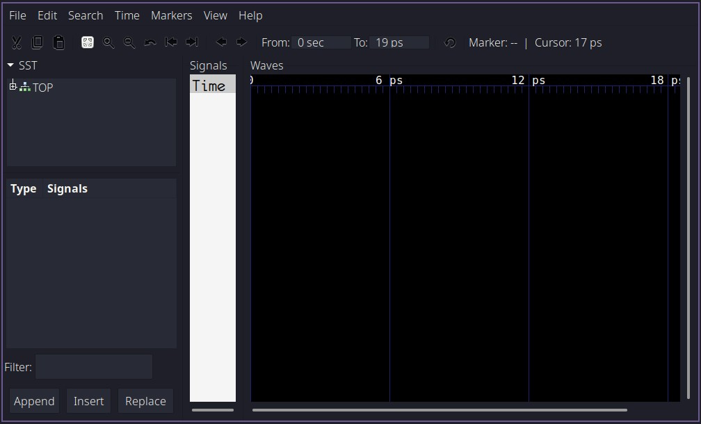 Fig. 3: GTKWave new window
Follow the steps shown here to load the signals from DUT and view their waveforms:
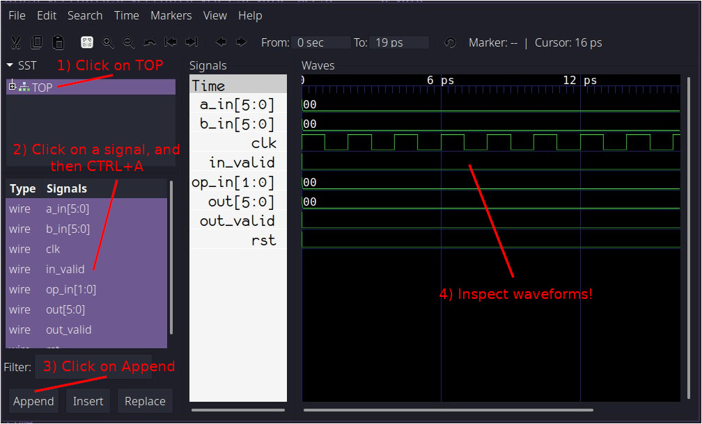 Fig. 4: GTKWave wave view
Congratulations! You’ve just completed your very first simulation using Verilator!
Observations ⌗
Firstly, you may have noticed that our simulation does not have any ‘x’, or unknown values. This is because Verilator is a two state simulator, and by default, all signals are initialized to 0. Great for speed, as 2 states is less than 4, but not great if we want to check how well our reset logic works. We will explore this more later.
Secondly, half of a clock cycle takes up 1ps. This is the default timescale for Verilator, and in this specific case it does not signify any particular value of time.
What’s next? ⌗
After reading this guide, you now hopefully have some basic understanding about how Verilator works. As you can see though, we’ve barely touched the surface, so please continue on to Part 2, where we will implement some basic verification funtionality into our C++ testbench.
If you have any questions or observations regarding this guide ⌗
Feel free to add me on my LinkedIn, I’d be happy to connect!
Or send me an email: