Verilator Pt.4: Modern transactional (UVM) style C++ testbench

In Part 1 and Part 2 we discussed the basics of using Verilator and writing C++ testbenches for Verilog/SystemVerilog modules, as well as some basic verification tasks: driving inputs, observing outputs, generating random stimulus and continuous assertion-like checking. In Part 3, we have built and explored a traditional style testbench written in C++.
In this guide, we will explore more modern verification technicques, specifically - UVM style transactional testbenches. If you have not encountered transactional style testbenches before, this tutorial will hopefully give you a solid understanding of how such testbenches work and are structured. On the other hand, if you have used UVM, this guide will give you some ideas on how to apply UVM concepts when building testbenches in raw C++.
Getting started ⌗
I will assume you have read and completed parts 1, 2 and 3 of my Verilator tutorial series before reading this guide. This part will be a bit different - instead of building our code step by step, we will explore a finished transactional style testbench, built upon the code from the previous parts.
The sources used in this tutorial are available on Github:
    git clone https://github.com/n-kremeris/verilator_basics
    git checkout verilator_pt4
What are transactional testbenches? ⌗
The always growing complexity of FPGA and ASIC designs brings along with it tougher verification requirements. The increased demand for advanced testbenches has therefore fueled the rise of new methodologies and tools, such as OVM, VVM, UVM, SystemC, as well as various python based frameworks. And all of these tools focus on a single goal - to facilitate building powerful, self-checking testbenches from reusable components, all while increasing code coverage, minimising code duplication, and allowing verification engineers to rest their eyes from staring at waveforms. One of the main ways the aforementioned tools achieve this goal is by encouraging the designer to write transactional style testbenches, which, as luck would have it, we can also do in raw C++ for use together with Verilator.
A transactional style testbench is a testbench that uses transactions (which is just a fancy term for exchanging of data or control packets) that provide an abstraction layer above directly assigning values to input pins and directly checking values of output pins of a Device-Under-Test (DUT). Confused? Let me explain.
A traditional style testbench written in VHDL, Verilog, SystemVerilog or C++ (like we saw in Part 1) will typically have an instance of the DUT, along with some long behavioral code with loops and conditional statements that sequentialy drives the DUT inputs to walk it through certain states. Most of the time, such testbenches are checked for correctness by visually inspecting waveforms, and although you could add self-checking capabilities via assertions or some monitoring code, this is not typically actively encouraged.
In contrast, a transactional testbench encourages strict separation between various functional blocks, each of which communicate via transactions. A basic transactional testbench could consist of:
- a block that generates stimulus data for the DUT (transaction generator / sequence)
- a block that drives the aforementioned data onto the DUT (driver)
- a block that observes the DUT’s outputs and generates result data packets (monitor)
- a block that collects various data packets, then compares them for correctness (scoreboard)
- a block that collects various data packets, and calculates functional coverage (coverage)
Immediately, a significant drawback of transactional testbenches is the complexity - due to the number of separate functional blocks that need to be built, it is much slower to get basic simulations going. However, what you get for the extra effort is unparalleled flexibility and reusability.
For example, if you have a driver in your testbench that supports an interface of type A, you can re-use the same exact driver with any other DUT that also has a type A interface - all that needs changing is the data you pass to it. If the type A interface gets swapped to an interface of type B, you just swap the driver block of said interface from type A to type B, and keep the rest of the testbench exactly the same.
Are transactional testbenches for me? ⌗
Yes, if you can spare the time to learn and deal with the extra complexity. Simple as that. The only exception to this, in my opinion, is if the DUT in question is very small - it might not be worth spending the extra time building and understanding transactional testbenches if you can whip up a finalized module in a couple of days.
Randomised transactional (UVM style) testbenches in raw C++ with Verilator ⌗
For those that are familiar with SystemVerilog UVM, you will be pleased to know that UVM-style testbenches can be written quite easily using raw C++. Structures similar to drivers, monitors, subscribers and scoreboards are simple to implement, and you can also implement coverage, as well as sequence-like structures with some additional effort.
Implementing modern transactional testbenches using raw C++ instead of SystemC and (or) using UVM-SystemC has the benefit of being much simpler to get started with, as well as in some cases providing much faster performance. The main downside is that a lot of things that are present in SystemC or UVM have to be reimplemented. In theory, one could also build a testbench using SystemVerilog UVM, convert that to C++ using Verilator, and use a basic C++ testbench to drive the verilated SV testbench. However, the support for UVM in Verilator is not quite there yet.
With all of that considered, this tutorial will explore implementing a basic transactional testbench in pure C++ without any additional libraries. We will do that by writing structures that loosely represent UVM transactions, drivers, monitors and a scoreboard. This will give you the required knowledge to start writing powerful C++ testbenches, as well as provide an understandable and easy-to-use foundation to build upon.
Basic transactional testbench block diagram ⌗
Here is a basic example of how a modern transactional testbench is structured:
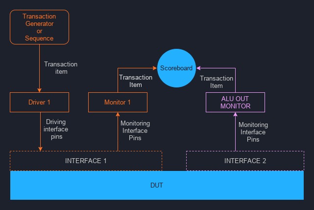 Fig. 1: Block diagram of a basic transactional testbench
If you’re new to this style of verification, the component names or terms might not be familiar. Here’s an explanation of what each of them are:
Transaction and Transaction item ⌗
A transaction is a high-level data exchange operation, and a transaction item is nothing more than a data packet, or in other words, a collection of data or instructions. They are typically implemented as a class or a struct, and contain data that is sent to or received from a DUT.
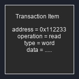 Fig. 2: Transaction item
Transaction generator ⌗
A transaction generator (you can also find it called a random transaction generator, stimulus generator, transaction item generator, or a random input generator) is a class or block of code that generates (creates) transaction items, which are used as instructions to drive input interfaces of the DUT.
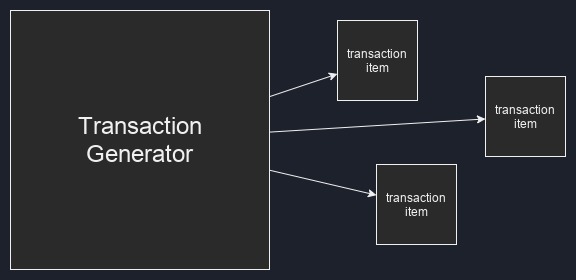 Fig. 3: Transaction generator
Driver ⌗
These structures are components that take transaction items and, based on the data inside said items, manipulate the physical pins of an input interface with 1’s and 0’s to drive data into a DUT. Drivers can also be required on complex output interfaces, where complex acknowledgements or handshakes are needed.
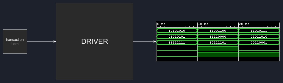 Fig. 4: Driver
Interface ⌗
An interface is just a collection or a group of pins that are used for a specific function. For example, a FIFO typically has two interfaces: an input, and an output, and a dual-clock RAM might have four: input for port A, output for port A, input for port B, output for port B.
An interface can be a class or a structure that aggregates functionally-related pins, or, as will be in our case, it can also be an implicit grouping of pins without any explicit grouping in code.
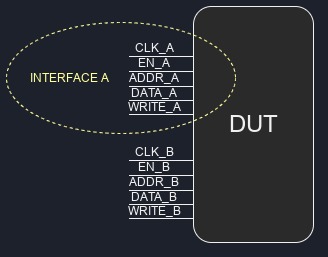 Fig. 5: Interface
Monitor ⌗
This is pretty much the exact opposite of a driver - instead of manipulating the physical pin states on interfaces, they instead passively observe (monitor) what’s happening on the interface. Monitors are typically connected to an output interface, where they are used to check the output of the device-under-test. Additionally, you can see them connected to input interfaces, where they can ensure that the associated driver drives the interface correctly.
What they do with the data resulting from the observed wave patterns is up to the testbench designer. Monitors can be fully self-contained and self-checking, meaning they can directly execute code that checks the correctness of the wave patterns as events happen on the interface. More typically however, monitors are designed to generate new transaction items from the observed interface pin state changes. These resulting transaction items are sent to analysis ports of scoreboards.
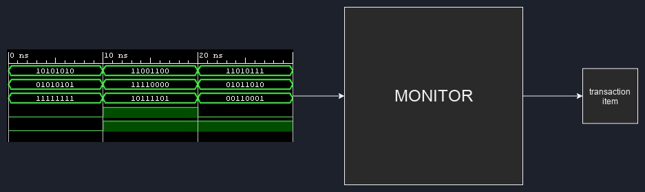 Fig. 6: Monitor
Scoreboard ⌗
The scoreboard structure typically contains the biggest chunk of the the self-checking testbench code. A single scoreboard has one or more analysis (listening) ports, which are used to receive transaction items from monitors. The scoreboard performs checks on the received transaction items to make sure the observed input stimuli result in correct outputs, and determines whether the testbench passes or fails.
Typically, you would have one single scoreboard in a testbench, but nothing is stopping you from building as many as you want.
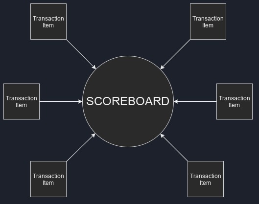 Fig. 7: Scoreboard
Now if you’re new to transactional style testbenches, you’re probably holding your head and thinking “I can’t make sense of any of this!”. Worry not - let’s explore how transactional testbenches work with something likely familiar to everyone reading this - coffee!
A roasty analogy ⌗
Imagine that you have just bought a new coffee machine and want to test it out. You invite your friend over too, who just happens to be a professional barista, for some help. Being a perfectionist, he demands that you give him exact instructions for your desired brew in the following format:
brew_info {
    brew_type;
    water_quantity;
    coffee_quantity;
    coffee_grind_size;
    cup;
}
So you grab a piece of paper, and generate the instructions for the perfect cup:
brew_info my_cup_config;
my_cup_config.brew_type = espresso
my_cup_config.water_quantity = 50g
my_cup_config.coffee_quantity = 25g
my_cup_config.coffee_grind_size = 7
my_cup_config.cup = small blue cup
and then hand over the my_cup_config to your friend, who then analyzes the information provided in this transaction item and starts to brew the cup exactly as described by driving the CUT (Coffeemaker-Under-Test) inputs. The coffee machine has an input interface that consists of buttons to start and stop the water flow, a dial to set the temperature, and others, and an output interface, a.k.a. the spouts.
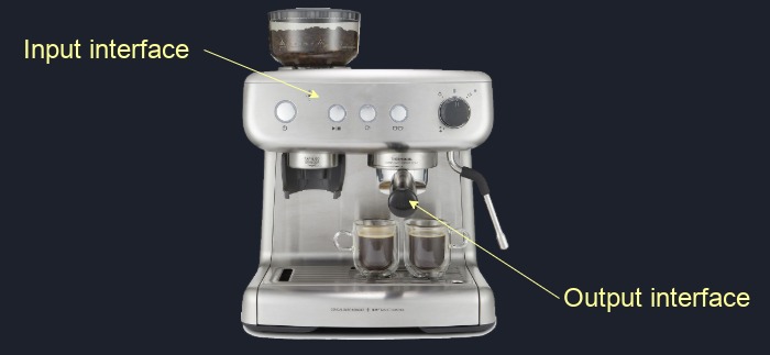 Fig. 8: The CUT and it's interfaces
You are confident in your friend’s abilities, so it’s unlikely that he will mess up your instructions. However, you ask your sister to stand next to the coffee machine just in case, and monitor the coffee making process while also writing down what she sees. And so she does:
brew_info observed_cup_config;
observed_cup_config.brew_type = espresso
observed_cup_config.water_quantity = 50g
observed_cup_config.coffee_quantity = 25g
observed_cup_config.coffee_grind size = 7
observed_cup_config.cup = small blue cup
As you can see, the coffee was observed to have been brewed just as required. However, in case your friend brews the coffee with cold water by accident or forgets to grind the beans beforehand, you will know, because you have the transaction item your sister wrote down and gave you.
Now, based on the fact that we are observing a coffee machine which we operate in a specific way, there are some immediate expectations. Firstly, it is expected of the coffee machine’s output interface to produce coffee, and not tea, hot chocolate or cola. Secondly, the coffee liquid is expected to have certain qualities as a result of the specific brewing process.
Once the coffee is served, you observe the cup, taste the coffee, monitor your experience, and take notes on another piece of paper as a true connoisseur:
coffee_characteristics the_coffee_chars;
the_coffee_chars.crema = lots;
the_coffee_chars.sweetness = average;
the_coffee_chars.strength = like a kick from a mule;
the_coffee_chars.cup = small blue cup;
Since you gave your friend specific instructions on how to prepare your black energy elixir, you know exactly what it should taste like. You can therefore use the data in observed_cup_config and the_coffee_chars to check if the coffee was brewed correctly using a scoreboard:
if observed_cup_config.brew_type == espresso then the_coffee.crema should be 'lots'
if observed_cup_config.water_quantity/coffee_quantity >= 2 then the_coffee.strength should be 'high'
// and so on...
If the cup matches your expectations, we can say that to our best knowledge, the coffee machine is operating correctly. Hopefully this analogy meets my expectations of giving you a better understanding too.
ALU transactional testbench structure and components ⌗
Similarly to the basic block diagram in Fig. 1, here’s the structure of the transactional testbench for our ALU:
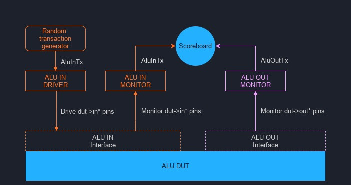 Fig. 9: Block diagram of our transactional testbench
If you have followed the getting started instructions above, we can now explore the code found in the testbench tb_alu.cpp.
AluInTx Transaction item ⌗
The ALU has an input interface consisting of pins op_in, a_in, b_in and in_valid. We therefore need a transaction item class that would be able to contain the data for driving said pins. This can be done with the following
class AluInTx {
    public:
        uint32_t a;
        uint32_t b;
        enum Operation {
            add = Valu___024unit::operation_t::add,
            sub = Valu___024unit::operation_t::sub,
            nop = Valu___024unit::operation_t::nop
        } op;
};
The numeric values for a_in and b_in can be easily contained in an unsigned 32 bit integer type uint32_t.
Verilator allows the use of uint8_t for signals that are up to 8 bits wide, uint16_t for up to 16, uint32_t for up to 32, and vluint64_t for up to 64 bits, and as long as the signal width is less than or equal to the size of the integer variable, and the compiler will up-convert as required. More info here.
For assigning an operation to the a and b operands, we create an enumerated op variable, with the enumerations given the values from the verilated SystemVerilog ALU code. This will save us from repeatedly writing the painful Valu___024unit::operation_t:: namespace prefix.
Lastly, we don’t need to keep info about in_valid in the AluInTx - the driver will take care of driving in_valid based on the generated AluInTx it receives.
rndAluInTx Transaction item generator ⌗
Now that we have the blueprint for the AluInTx transaction, we need some code to create transaction item objects and assign some values to the operands. This is done in the transaction generator:
AluInTx* rndAluInTx(){
    //20% chance of generating a transaction
    if(rand()%5 == 0){
        AluInTx *tx = new AluInTx();
        tx->op = AluInTx::Operation(rand() % 3); // Our ENUM only has entries with values 0, 1, 2
        tx->a = rand() % 11 + 10; // generate a in range 10-20
        tx->b = rand() % 6;  // generate b in range 0-5
        return tx;
    } else {
        return NULL;
    }
}
Each time the rndAluInTx() function is called, it will randomly either
-
allocate memory for an
AluInTxobject (line 4), assign random values toop,aandb, and return a pointer to the newly generated object upon exiting (line 8). -
immediately return NULL as the pointer value (line 10), signifying a transaction was not generated.
The reason for randomly skipping generating every other transaction is to allow for gaps between commands being issued to the ALU. Returning a NULL is not the only way of achieving this - you could instead go the entirely opposite way and create a sequence (see here) that depends on some time variable (for example, the simulation ticks, or a positive edge counter), and then generate transactions only at specific times.
AluInDrv Input interface driver ⌗
Once we generate an AluInTx transaction item using the rndAluInTx generator, the AluInTx gets passed to a driver block that drives the ALU input interface using the information in the transaction item. Here is the driver code from our testbench:
class AluInDrv {
    private:
        Valu *dut;
    public:
        AluInDrv(Valu *dut){
            this->dut = dut;
        }

        void drive(AluInTx *tx){
            // we always start with in_valid set to 0, and set it to
            // 1 later only if necessary
            dut->in_valid = 0;

            // Don't drive anything if a transaction item doesn't exist
            if(tx != NULL){
                if (tx->op != AluInTx::nop) {
                    // If the operation is not a NOP, we drive it onto the
                    // input interface pins
                    dut->in_valid = 1;
                    dut->op_in = tx->op;
                    dut->a_in = tx->a;
                    dut->b_in = tx->b;
                }
                // Release the memory by deleting the tx item
                // after it has been consumed
                delete tx;
            }
        }
};
The AluInDrv constructor requires a handle to the dut object. We need to have a handle to the device-under-test inside drivers / monitors to have access to the DUT pins.
On line 12, you can see that the in_valid input is always driven to 0 by default. This is because unless we have a valid AluInTx, and the AluInTx is also not a NOP, the input to the ALU will not be valid. The below SV code would be a rough equivalent:
always_comb begin
    dut.in_valid = 1'b0;
    if ( tx item exists && tx item operation != NOP ) begin
        dut.in_valid = 1'b1;
    end
end
If the transaction item was not NULL, then line 26 deletes (deallocates) the associated memory where the transaction item object lives. This is highly important to do - once the item is used (driven into the DUT), it’s lifetime is over, and it must be deleted, otherwise we will have a memory leak.
Note that C++ supports smart memory management, which I highly recommend you to use. However, for explanation purposes, I believe manual memory management better illustrates the lifetime of transaction items.
AluInMon input interface monitor ⌗
The AluInMon monitors the input interface of the ALU, meaning it does exactly the opposite of the driver that was discussed in the previous section.
class AluInMon {
    private:
        Valu *dut;
        AluScb *scb;
    public:
        AluInMon(Valu *dut, AluScb *scb){
            this->dut = dut;
            this->scb = scb;
        }

        void monitor(){
            if (dut->in_valid == 1) {
                // If there is valid data at the input interface,
                // create a new AluInTx transaction item and populate
                // it with data observed at the interface pins
                AluInTx *tx = new AluInTx();
                tx->op = AluInTx::Operation(dut->op_in);
                tx->a = dut->a_in;
                tx->b = dut->b_in;

                // then pass the transaction item to the scoreboard
                scb->writeIn(tx);
            }
        }
};
Here you can see that on line 12, we observe the in_valid input to the ALU. If the input is valid, the monitor creates a new AluInTx transaction item, grabs the values of op_in, a_in, b_in pins, and stuff them into the AluInTx variables op, a, and b.
This newly generated transaction item tells us what operation we have sent into the ALU’s inputs, which will be needed to check whether the outputs of the ALU are correct. Therefore, on line 22, the new transaction item is written into the scoreboard for later use.
AluOutTx transaction item ⌗
Just like we needed an AluInTx transaction item for operations involving the input interface, we need an AluOutTx transaction item for storing information about the results coming out from the output interface.
However, because the only information that we get from the output interface is a single result value, the AluOutTx only consists of a single variable:
class AluOutTx {
    public:
        uint32_t out;
};
AluOutMon output interface monitor ⌗
Here is where the AluOutTx item comes into play. Just like the input interface monitor, the AluOutMon observes the output interface in exactly the same manner:
class AluOutMon {
    private:
        Valu *dut;
        AluScb *scb;
    public:
        AluOutMon(Valu *dut, AluScb *scb){
            this->dut = dut;
            this->scb = scb;
        }

        void monitor(){
            if (dut->out_valid == 1) {
                // If there is valid data at the output interface,
                // create a new AluOutTx transaction item and populate
                // it with result observed at the interface pins
                AluOutTx *tx = new AluOutTx();
                tx->out = dut->out;

                // then pass the transaction item to the scoreboard
                scb->writeOut(tx);
            }
        }
};
The AluOutMon patiently waits for the out_valid signal to be asserted to 1. When that happens, a new AluOutTx item is generated (line 16), the value on the DUT output pins is saved into the out variable in the AluOutTx item, and then the item is passed into the scoreboard.
AluScb scoreboard ⌗
The scoreboard is, in my opinion, the most important block in the testbench - it is the main brain of this entire operation. The scoreboard is the place where all the truth about life, the universe, and everything is kept, and also enforced:
// ALU scoreboard
class AluScb {
    private:
        std::deque<AluInTx*> in_q;

    public:
        // Input interface monitor port
        void writeIn(AluInTx *tx){
            // Push the received transaction item into a queue for later
            in_q.push_back(tx);
        }

        // Output interface monitor port
        void writeOut(AluOutTx* tx){
            // We should never get any data from the output interface
            // before an input gets driven to the input interface
            if(in_q.empty()){
                std::cout <<"Fatal Error in AluScb: empty AluInTx queue" << std::endl;
                exit(1);
            }

            // Grab the transaction item from the front of the input item queue
            AluInTx* in;
            in = in_q.front();
            in_q.pop_front();

            switch(in->op){
                // A valid signal should not be created at the output when there is no operation,
                // so we should never get a transaction item where the operation is NOP
                case AluInTx::nop :
                    std::cout << "Fatal error in AluScb, received NOP on input" << std::endl;
                    exit(1);
                    break;

                // Received transaction is add
                case AluInTx::add :
                    if (in->a + in->b != tx->out) {
                        std::cout << std::endl;
                        std::cout << "AluScb: add mismatch" << std::endl;
                        std::cout << "  Expected: " << in->a + in->b
                                  << "  Actual: " << tx->out << std::endl;
                        std::cout << "  Simtime: " << sim_time << std::endl;
                    }
                    break;

                // Received transaction is sub
                case AluInTx::sub :
                    if (in->a - in->b != tx->out) {
                        std::cout << std::endl;
                        std::cout << "AluScb: sub mismatch" << std::endl;
                        std::cout << "  Expected: " << in->a - in->b
                                  << "  Actual: " << tx->out << std::endl;
                        std::cout << "  Simtime: " << sim_time << std::endl;
                    }
                    break;
            }
            // As the transaction items were allocated on the heap, it's important
            // to free the memory after they have been used
            delete in;
            delete tx;
        }
};
Wow, this is one big chunk of code. Starting off at the top, a queue is created for the scoreboard to keep AluInTx transaction items:
std::deque<AluInTx*> in_q;
Each time a valid operation is sent to the ALU, the input interface monitor writes an AluInTx item into the scoreboard via the writeIn method (line 8). The AluInTx item needs to be compared to a corresponding AluOutTx item to see if the ALU results are correct. As the ALU is pipelined, multiple commands can be sent into the input interface before any AluOutTx result items are received. Therefore, the AluInTx items need to be stored for later until the required AluOutTx items are written into the scoreboard, and a queue is the perfect container for this application.
The writeOut (line 14) method is where all of the result checking happens. Firstly, on line 17, we check the ALU is not generating random garbage at the output - we know that we should only observe results at the output interface if a valid operation was issued at the input some time ago, so there should never be a point in time where we have a result available in the scoreboard before at least a single AluInTx is available in the queue.
Next, if the in_q queue is not empty, we pop the first (oldest) AluInTx item from the start of the queue, and then proceed to the switch statement on line 27. The first case in the switch (line 30) is a check for correct testbench behavior - a valid signal should not be asserted at the input interface if the operation is NOP, therefore, if anAluInTx with an operation of NOP is received in the scoreboard, then we could suspect that the AluInDrvis not working right.
In the remaining cases, depending on whether the AluInTx is an addition operation (line 36), or a subtraction operation (line 47), we add or subtract the original operands stored in the AluInTx packet we grabbed from the queue, and check that the result received in AluOutTx transaction item matches the calculated expected result.
Lastly, at the end of the writeOut method, the transaction items we compared are no longer useful, and they are therefore deleted on lines 59 and 60.
The mighty main loop and how everything ties together ⌗
This is it - the final piece of the puzzle. The main loop is where all of the verification magic happens. The main function contains the instantiations of the testbench blocks (the monitors, driver, scoreboard), and the main loop then iteratively executes all of the testbench block functionality until the simulation is finished. That, or the testbench fails miserably and we exit prematurely. Here is the code to the main function and the main simulation loop:
int main(int argc, char** argv, char** env) {
    <...>

    AluInTx   *tx;

    // Here we create the driver, scoreboard, input and output monitor blocks
    AluInDrv  *drv    = new AluInDrv(dut);
    AluScb    *scb    = new AluScb();
    AluInMon  *inMon  = new AluInMon(dut, scb);
    AluOutMon *outMon = new AluOutMon(dut, scb);

    while (sim_time < MAX_SIM_TIME) {
        dut_reset(dut, sim_time);
        dut->clk ^= 1;
        dut->eval();

        // Do all the driving/monitoring on a positive edge
        if (dut->clk == 1){

            if (sim_time >= VERIF_START_TIME) {
                // Generate a randomized transaction item of type AluInTx
                tx = rndAluInTx();

                // Pass the transaction item to the ALU input interface driver,
                // which drives the input interface based on the info in the
                // transaction item
                drv->drive(tx);

                // Monitor the input interface
                inMon->monitor();

                // Monitor the output interface
                outMon->monitor();
            }
        }
        // end of positive edge processing

        m_trace->dump(sim_time);
        sim_time++;
    }

    <...>
    delete dut;
    delete outMon;
    delete inMon;
    delete scb;
    delete drv;
    exit(EXIT_SUCCESS);
}
Lets take a look at how this all works. Once the testbench blocks are instantiated (lines 14-17), the simulation enters the main loop in line 19, which is run until the simulation time is over.
At each iteration of the main loop, we check if we are at a positive clock edge (line 25), and if so, the testbench will generate an AluInTx transaction (line 28).
The AluInTx transaction item is passed onto the AluInDrv driver (line 33), which then drives the ALU input pins based on the info inside said item.
At the same clock edge, the AluInMon monitor observes the ALU input pins (line 36), and from the input pin observation creates a new AluInTx transaction item that gets written into the scoreboard.
Still on the same clock edge, the AluOutMon monitor observes the ALU output pins (line 39), but no AluOutTx transactions are created yet, because of the ALU pipeline latency. It takes at least two iterations of the main loop, before the AluOutMon will start to see results coming out of the ALU.
Finally, once the simulation is finished and the main loop is done, all the testbench blocks are deleted to deallocate memory (lines 46-50).
Simulation ⌗
Now that you know how the testbench works, you should try simulating and exploring the results. If you have cloned the project sources, running make in the project folder will build and run the transactional testbench. It won’t print any interesting output by default, however, because both the ALU and the testbench behave correctly and the testbench passes without any errors.
That’s not very exciting, so let’s take a look at what happens when something goes wrong.
ALU bad results ⌗
This is a straightforward problem to detect - if the ALU returns bad results, the scoreboard will immediately complain. If we modify the ALU output code like so:
out       <= 6'h5; //should be "<= result"
out_valid <= in_valid_r;
Then the scoreboard will swiftly detect the wrong results:
AluScb: add mismatch
  Expected: 15  Actual: 5
  Simtime: 204

AluScb: sub mismatch
  Expected: 11  Actual: 5
  Simtime: 234

AluScb: add mismatch
  Expected: 17  Actual: 5
  Simtime: 236
ALU unexpected out_valid ⌗
If we modify the ALU so that the output is always valid, for example:
out       <= result;
out_valid <= 1'b1; //should be "<= in_valid_r"
Then the testbench will immediately quit with a fatal error upon the first encounter of a stray valid output:
./obj_dir/Valu +verilator+rand+reset+2
Fatal Error in AluScb: empty AluInTx queue
make: *** [Makefile:23: waveform.vcd] Error 1
This is because the scoreboard does not expect to see output data at the output interface if there was no command driven on the input interface some time beforehand (see here).
Waves! ⌗
If you have GTKWave set up on your system, you can run make waves in the project folder to see the how the randomly generated transactions look:
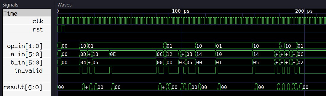 Fig. 10: Waves!
Conclusion ⌗
After the massive pile of text presented above, I am certain you made plenty of conclusions about Verilator and transactional testbenches on your own, so I needn’t write anything. Personally, I have concluded that I will continue using and pushing for Verilator and raw C++ testbenches for the forseeable future wherever possible, as the price, speed and flexibility are too hard to pass up. What about you?
What’s next? ⌗
Ideally, we’d have some extra checks in the rndAluInTx() transaction generator function. Additionally, the testbench is lacking a highly important check that should be done before exiting. I can give you a hint: in_q. If you think you know what should be added, send me a message on LinkedIn to see if you’re correct! :)
Lastly, the code can be made much nicer by using modern C++ features, for example, replacing the AluInTx, AluOutTx raw pointers with smart pointers. The sky is the limit!
There are also other blocks to explore, like sequences, listeners, coverage blocks (see Appendix A). A good exercise would be to try implementing them in this testbench.
If there is a demand for specific Verilator or GTKwave related content, I might consider writing something extra. Why not let me know what’s missing? Feel free to add me on my LinkedIn, or send me an email: 
Further reading ⌗
(external links)
Appendix A: Other terms/components you may encounter ⌗
A sequence can be a block of code that replaces or augments the transaction generator. A sequence is exactly that as named - it is essentially a list of steps that describes what the testbench is supposed to do at specific times. A sequence can contain, for example, steps that create a single transaction or multiple transactions with specific values, or with randomized values, or do other tasks such as configuring various testbench blocks, or checking results in complex sequential or time-based ways that can’t be easily done in monitors or scoreboards. To complete tasks/checks at specific times, a sequence can be made to use time keeping variables (for example simulation time counter, posedge counter, negedge counter).
A listener, also known as a subscriber, is like a smaller, single port version of a scoreboard. It can contain some interface-specific checking code that perhaps does not fit well with the other stuff contained in the main scoreboard.
Coverage is a term used to describe the thoroughness of the verification. For example, if you are verifying a RAM module, the only way to make sure your module works correctly with all addresses, is to simulate read/write operations to the entire address range. This is equivalent to full coverage.
Consequently, if you only check that read/write operations work at address 0, your test may pass successfully, but your coverage will be almost non-existent.
If, however, you test a broad range of random addresses, you will have a respectable coverage and you can expect that, to a degree, your module will work correctly across the entire address range. This saves you simulation time, because instead of checking every single possible address, you may choose to simulate read/write operations to the extremes (min and max addresses), and a few random addresses across the range.
A coverage block is similar to a scoreboard, in that it listens to one or more monitors, however, instead of checking for correctness, it logs and reports coverage, which means tracking what kind of inputs, outputs and states of the DUT have been observed. Going back to the RAM module example, you may want to ensure you hit every single address possible, or, maybe just the min, max, as well as an arbitrary number of addresses in the remaining range.